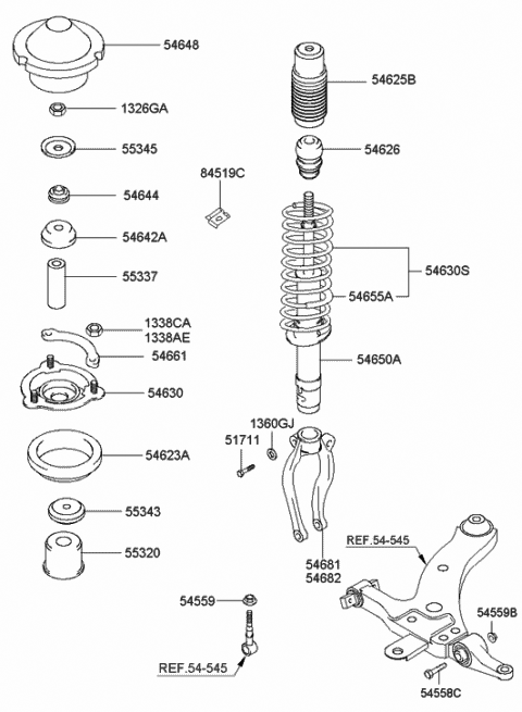
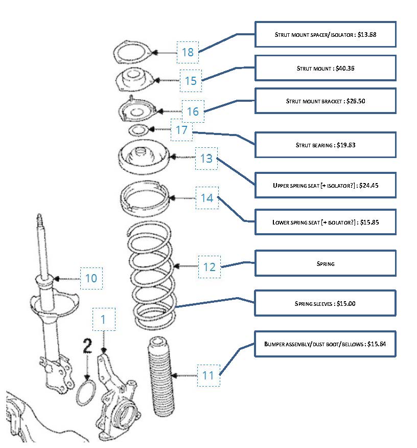
Strut Assembly Diagram
These are the original end link sway bar and tab locations for a 1970 B-Body. Place the strut assembly back into the vehicle.
 54611 38601 Genuine Hyundai Strut Assembly
Position the stabilizer link to the strut assembly and install the retaining nut.
Strut assembly diagram. A conventional lower control arm attaches to the frame and to the lower ball joint. Here is a picture gallery about front end suspension parts diagram complete with the description of the image please find the image you need. Tighten the nut to 90-100 Nm 66-74 lb-ft.
Earlier lower control arms have the tab mounted farther out on the control arm and use a different style sway bar. Sometimes the term strut refers to the shock absorber portion only but other times the term is used to denote the entire assembly including the spring. Strut diagrams give a pictorial description of a struts assembly including a breakdown of individual.
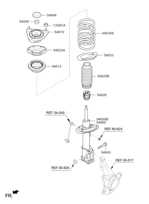
Tj Wrangler Suspension And Steering 4 Wheel Parts intended for Front End Suspension Parts Diagram image size 630 X 739 px and to view image details please click the image. In a MacPherson strut type suspension only one control arm and a strut is used to support each wheel assembly. Slide the new strut assembly up into the spring and reposition the top mount onto the spring in the same position that it was removed.
We pride ourselves on our superb personal customer service. Install the retaining washer and top nut. Sway Bar Link Kits.
A MacPherson strut uses a hub carrier with two mounting points that connect and dictate orientation of the wheel assembly. The struts axis may be angled inwards from the steering axis at the bottom. The ball joint holds the control arm to the steering knuckle or bearing support.
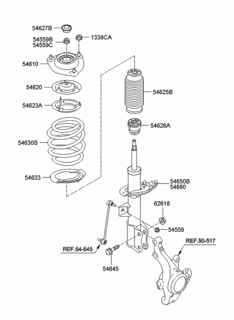
The top of the steering knuckle or bearing support is bolted to the strut. The axis of the strut itself is the upper steering pivot. Learn how to replace a strut assembly on your vehicle with the help of our experts at Prime Choice Auto Parts and save up to 70 on the parts youll need to.
How Does a MacPherson Strut Work. This video shows how to remove the front strut and spring assembly from a VE Commodore. Unscrew the bolts that link the struts to the hub and pull out the strut assembly from the car.
All the nuts and bolts are black phosphate. When the front wheels are steered the entire strut will pivot from the lower ball joint to the upper strut mount. Note the bolt inserted from the bottom up.
Please keep in mind this is just for representation purposes and your cars strut assembly. Some strut assemblies also include other parts such as a spring isolator or mount bearings. Position the strut assembly to the steering knuckle.
A MacPherson strut assembly is made up of the strut bumpstop or boot spring springseat and mount. By utilizing a hub carrier or steering knuckle with two mounting points a MacPherson. Then mark the top mounting location for future reference.
Dont trust a part designed to fit multiple vehicles and dont trust anything less than KYB. Strut assembly Diagram - Strut assembly Diagram Kenmore Model K113 Dishwasher Genuine Parts. A complete strut assembly is a combination of two main parts.
The upper part of the hub carrier is rigidly fixed to the bottom of the outer part of the strut proper. Pull strut assembly out from the bottom of spring. Depending on the type of strut and whether it is rear or front these diagrams include the cover snap ring shim and cotter pin.
Tighten the top nut to the manufacturers specifications and carefully remove the spring compressor. This slides up and down the inner part of it which extends upwards directly to a mounting in the body shell of the vehicle. A strut assembly handles vehicle weight determines ride height acts as the steering pivot controls vehicle stability and can affect a vehicles electronic crash avoidance systems.
The line from the struts top mount to the bottom ball joint on the control arm gives the steering axis inclination. Install the front wheel and tire assembly. A spring and a shock absorber.
Engineered to help carry the vehicle load and transfer that load to the spring and strut housing OE-quality bearing serves as the upper pivot point and forms the steering axis. Here is a quick and easy visual of a typical strut assembly. Install the pinch bolt and tighten it to 115-132 Nm 85-97 lb-ft.
Our OEM parts section provides full assembly diagrams and part lists for every Honda Kawasaki BRP BMW Kymco Ducati Polaris Suzuki and Yamaha motorcycles ATVs personal watercraft snowmobiles and dirt bikes.
 Strut Diagram Rear Wiring Diagram Overview Circuit Halt Circuit Halt Aigaravenna It
 Strut Design Monroe Shock Absorbers
 Amazon Com Toyota 48520 09894 Suspension Strut Assembly Automotive

 Amazon Com Mazda Zzd1 34 900 Suspension Strut Assembly Automotive

 54651a7200 Genuine Kia Strut Assembly Front Lh
 Front Strut Mount Diagram Page 1 Line 17qq Com
 Replace Front Struts On Toyota Sienna 2004 2010 Share Your Repair
 54651 3x151 Genuine Hyundai Strut Assembly Front Lh
 3 Macpherson Strut Download Scientific Diagram
 Strut Design Monroe Shock Absorbers
 Strut Assembly Parts Opinions Maxima Forums


Comments
Post a Comment