Electrical Outlet Wiring
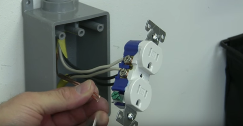
The outlet should be wired to a dedicated 20-amp240-volt circuit breaker in the service panel using 122 awg cable. The black wire line and white neutral connect to the receptacle terminals and another 2 wire NM that travels to the next receptacle.
 Socket Outlet Wiring Amazing Procedure What Is Socket Outlet Socket Outlet Is A Device With Protected Current Carrying As Outlet Wiring Sockets Plug Socket
Your cable should be long enough to reach each socket.

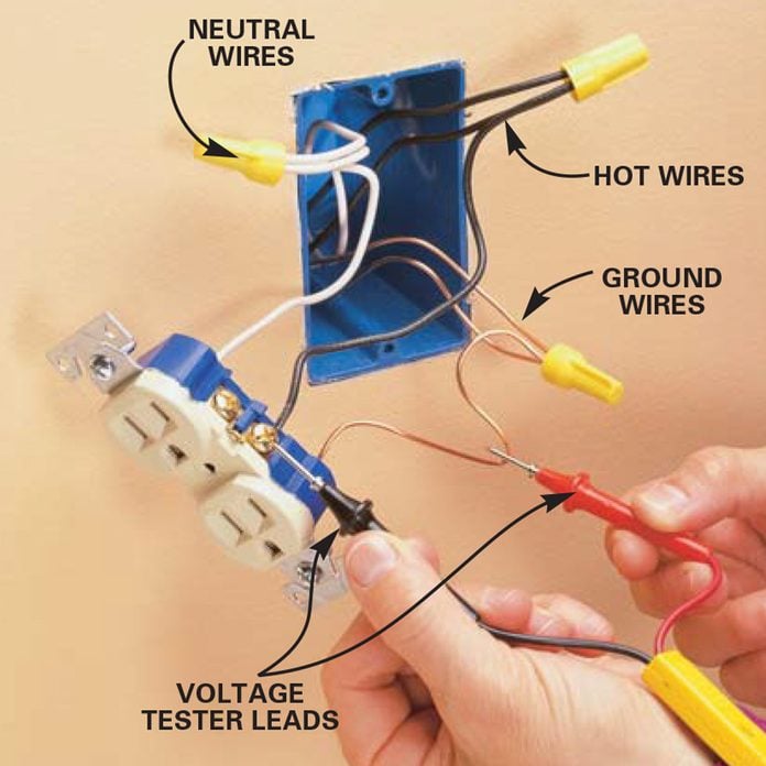
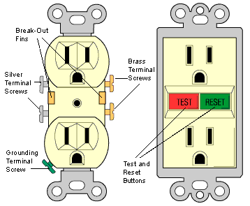
Electrical outlet wiring. Make sure there really is NO power to your wires. This repeats until the end of. A standard electrical outlet has two brass terminal screws two chrome ones and a single ground terminal which is green.
In modern electrical circuits used to wire receptacles electrical outlets. On the other hand if y. Httpsamznto2NHHKuSIf you are a pro this video might be a snoozer.
The neutral wire from the circuit is shared by both sets. One cant be too careful. With this wiring both the black and white wires are used to carry 120 volts each and the white wire is wrapped with electrical tape to label it hot.
Run the cable from the circuit breaker to the location of the electrical outlet. According to NEC an outlet is the points in an electrical wiring system where current can be taken and utilize by electrical appliances and equipment by plugging them in it. First things first go to your breaker box and flip off the power to the location in question.
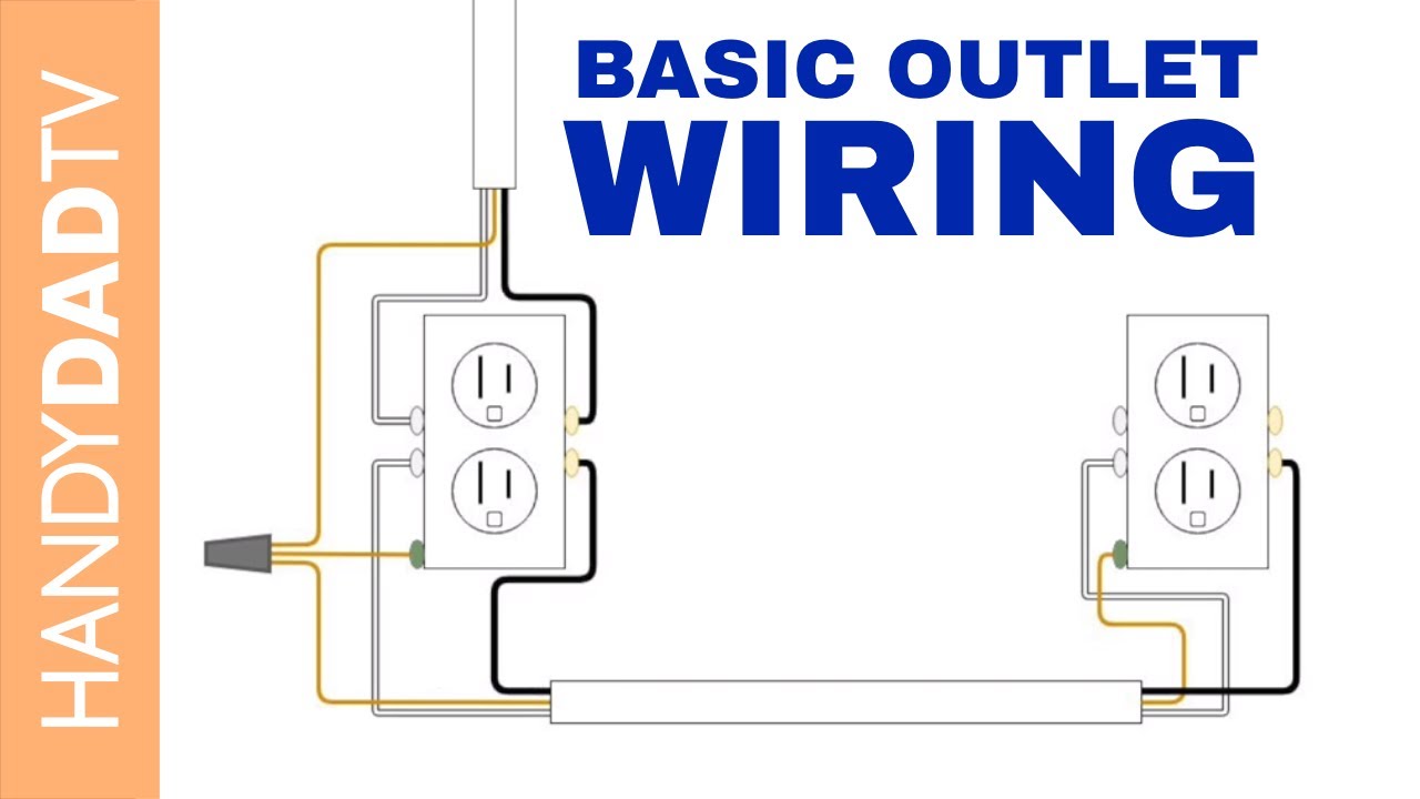
Usually receptacles approved for aluminum wiring will get stamped COALR CU-AL or AL-CU indicating they may get used for both copper and aluminum. More modern decora switches and outlets are not aluminum wire rated. In the diagram below a 2-wire NM cable supplies line voltage from the electrical panel to the first receptacle outlet box.
How To Wire An Electrical Outlet. Typically an electrical receptacle is wired with two insulated wires and a bare ground wire all three of which are encased in a plastic NMC or metal BX jacket. These are some of the things that need to be check.
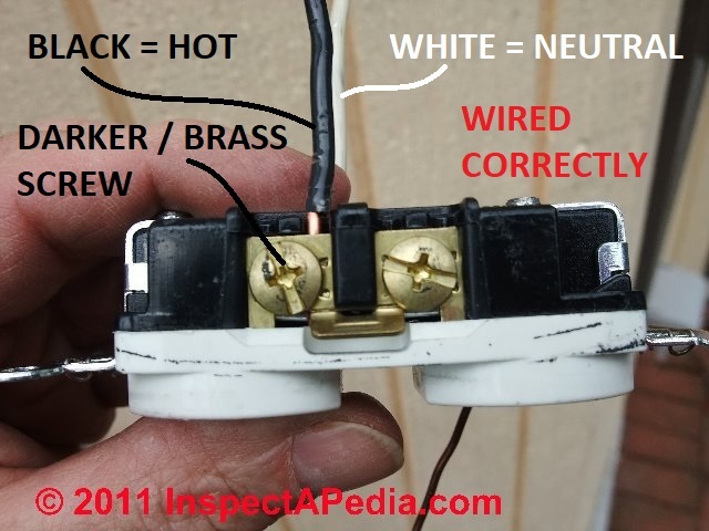
When you wire a single outlet to a live circuit cable you connect the black wire to one of the brass screws usually the top one but it doesnt matter and the white wire to one of the chrome screws. They are the biggest safety hazard and when the outlet gets loose the wiring inside the outlets will get heated and then the energy that will be generated will get out in the form of an electrical arc. Switch off the mains.
This wiring is commonly used in a 20 amp kitchen circuit where two appliance feeds are needed such as for a refrigerator and a microwave in the same location. Pull electrical cable into junction box. Some duplex outlets can have different circuits running to adjacent outlets.
This outlet is commonly used for a heavy load such as a large air conditioner. Here 3-wire cable is run from a double-pole circuit breaker providing an independent 120 volts to two sets of multiple outlets. Examine a conventional duplex receptacle and youll see that the two brass screws and the two chrome ones are joined by conducting plates.
SHUT OFF YOUR POWER SUPPLY. Youll see this wire labeled as 142 Type NM B with groun d photo at left or 142 Type NM C with ground. Before doing any wiring plug the radio into other outlets you plan to work on.
This energy that comes out can melt the plastic as well as metal and can cause a fire. When buying replacement electrical outlets for aluminum wiring ensure that all are compatible. Electrical Outlet Wiring Instructions for Homeowners DIY Repairs.
You should switch off electrical power from the mains to avoid electrocution. The Electrical Power Source Enters at the Switch Outlet Wiring for a Table Lamp or a Floor Light Fixture These electrical wiring diagrams show typical connections. You can wire a split-tab circuit with any duplex outlet rated for the ampacity of the circuit except for a GFCI or AFCI outlet because you cant modify either of these to separate the outlets.
An outlet receptacle where one or more receptacle are installed or a supply contact device installed at the outlet to connect an electrical load through plugs and switches. Our photo at page top illustrates other wire connections shown out of the electrical box and thus is not an example of a proper electrical outlet installation. To be safe test both the top and bottom with the radio.
Electrical outlet wiring Step 1. The diagram below shows the power entering the circuit at the grounded outlet box location then sending power up to the switch and a switched leg back down to the outlet. Our photo left shows the black or hot wire connected to the brass-colored screw on an electrical receptacle.
A circuit breaker finder is a handy tool for finding the right breaker. But dont assume the electricity is off in all the other outlets or lights in the room.
 Wiring Diagram For A Grounded Outlet
 How To Install An Electrical Outlet From A Sub Panel
 How To Wire An Electrical Outlet Youtube
 How To Install A New Electrical Outlet Socket Receptacle In Your Home Youtube
 How To Wire An Outlet And Add An Electrical Outlet Diy Family Handyman
 Split Plug Wiring Diagram Basic Electrical Wiring Electrical Wiring Home Electrical Wiring
 21 Outlet Has Power But Doesn T Work Lawand Biodigest
15 Electric House Ideas Electric House Diy Electrical Home Electrical Wiring
 Wiring Diagram Electrical Outlet
 How To Wire An Outlet Reality Daydream
 How To Wire An Outlet And Add An Electrical Outlet Diy Family Handyman
 How Electrical Receptacles Work Hometips
:max_bytes(150000):strip_icc()/AddtheRedWire-22359a8c11074fc28a7219d89d0b5980.jpg) How To Wire Split Outlets
How To Wire Split Outlets
 110 Plug Wiring Method Fusebox And Wiring Diagram Symbol Lot Symbol Lot Sirtarghe It


Comments
Post a Comment